

How to configure a cross arm beam sensor?
Leave a message

Cross arm beam sensors are essential components in various industrial and commercial applications, offering high precision in force and weight measurement. As a supplier of these sensors, I understand the importance of proper configuration to ensure optimal performance. In this blog post, I'll guide you through the process of configuring a cross arm beam sensor, sharing insights and best practices based on my experience in the industry.
Understanding the Cross Arm Beam Sensor
Before diving into the configuration process, it's crucial to have a basic understanding of what a cross arm beam sensor is and how it works. A cross arm beam sensor is a type of load cell that uses strain gauges to measure the deformation caused by an applied force. The sensor consists of a metal beam with strain gauges attached to its surface. When a force is applied to the beam, it deforms, and the strain gauges change their electrical resistance. This change in resistance is then converted into an electrical signal proportional to the applied force.
Cross arm beam sensors are known for their high accuracy, reliability, and durability. They are commonly used in applications such as industrial weighing systems, force measurement in robotics, and material testing. To learn more about our range of cross arm beam sensors, visit Cross Arm Beam Sensor.
Step 1: Selecting the Right Sensor
The first step in configuring a cross arm beam sensor is selecting the right sensor for your application. Several factors need to be considered when making this decision, including the maximum load capacity, accuracy requirements, and environmental conditions.
- Load Capacity: The load capacity of the sensor should be selected based on the maximum force or weight that will be applied during normal operation. It's important to choose a sensor with a load capacity slightly higher than the expected maximum load to prevent overloading and ensure long-term reliability.
- Accuracy Requirements: The accuracy of the sensor is determined by its sensitivity and linearity. Higher accuracy sensors are typically more expensive but may be necessary for applications that require precise force or weight measurement.
- Environmental Conditions: The environmental conditions in which the sensor will be used can also affect its performance. Factors such as temperature, humidity, and vibration should be considered when selecting a sensor. For harsh environments, sensors with additional protection features such as waterproofing or shock resistance may be required.
If you're unsure which sensor is right for your application, our team of experts can provide you with personalized advice and recommendations. You can also explore our range of Single point force sensors and Parallel Beam Load Cell to find the perfect solution for your needs.
Step 2: Mounting the Sensor
Once you have selected the right sensor, the next step is to mount it properly. Proper mounting is essential to ensure accurate and reliable measurement. Here are some guidelines to follow when mounting a cross arm beam sensor:
- Surface Preparation: The mounting surface should be clean, flat, and free of any debris or contaminants. Any irregularities on the surface can affect the sensor's performance and accuracy.
- Alignment: The sensor should be mounted in a way that ensures the applied force is perpendicular to the sensing axis. Misalignment can cause inaccurate measurement and reduce the sensor's lifespan.
- Fastening: The sensor should be securely fastened to the mounting surface using the appropriate hardware. Over-tightening the fasteners can damage the sensor, while under-tightening can cause the sensor to move or vibrate, leading to inaccurate measurement.
Step 3: Wiring the Sensor
After mounting the sensor, the next step is to wire it to the measurement system. The wiring process may vary depending on the type of sensor and the measurement system being used. Here are some general guidelines to follow when wiring a cross arm beam sensor:
- Understand the Wiring Diagram: Before wiring the sensor, it's important to understand the wiring diagram provided by the manufacturer. The wiring diagram will show you how to connect the sensor to the measurement system, including the power supply, signal output, and ground connections.
- Use the Right Cable: The cable used to connect the sensor to the measurement system should be of the appropriate type and length. The cable should be shielded to prevent electromagnetic interference (EMI) and ensure accurate measurement.
- Proper Termination: The cable should be properly terminated at both ends to ensure a secure and reliable connection. Loose or improper connections can cause signal loss, noise, and inaccurate measurement.
Step 4: Calibrating the Sensor
Calibration is an essential step in configuring a cross arm beam sensor. Calibration ensures that the sensor provides accurate and reliable measurement by adjusting the output signal to match a known reference value. Here's how you can calibrate a cross arm beam sensor:
- Use a Calibration Weight: To calibrate the sensor, you'll need a calibration weight with a known mass. The calibration weight should be placed on the sensor, and the output signal should be measured using a calibrated measurement system.
- Adjust the Zero Point: The zero point of the sensor should be adjusted so that the output signal is zero when no load is applied. This can be done by adjusting the zero adjustment potentiometer on the sensor or the measurement system.
- Adjust the Span: The span of the sensor should be adjusted so that the output signal is proportional to the applied load. This can be done by adjusting the span adjustment potentiometer on the sensor or the measurement system.
Step 5: Testing and Verification
Once the sensor has been calibrated, it's important to test and verify its performance. Testing and verification ensure that the sensor is working properly and providing accurate measurement. Here's how you can test and verify a cross arm beam sensor:

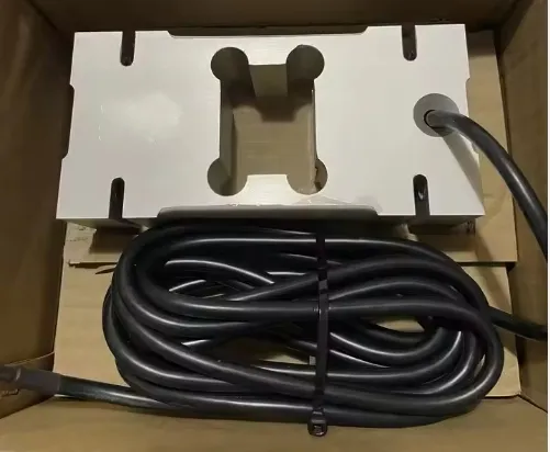
- Apply a Known Load: Apply a known load to the sensor and measure the output signal using a calibrated measurement system. Compare the measured output signal with the expected output signal based on the calibration data.
- Check for Linearity: Check the linearity of the sensor by applying a series of increasing loads and measuring the output signal at each load. The output signal should increase linearly with the applied load.
- Check for Repeatability: Check the repeatability of the sensor by applying the same load multiple times and measuring the output signal each time. The output signal should be consistent within a specified tolerance.
Step 6: Troubleshooting
Even after proper configuration and calibration, issues may still arise with the cross arm beam sensor. Here are some common issues and their possible solutions:
- Inaccurate Measurement: Inaccurate measurement can be caused by several factors, including misalignment, overloading, or calibration errors. Check the mounting and alignment of the sensor, ensure that the load is within the sensor's capacity, and re-calibrate the sensor if necessary.
- Signal Noise: Signal noise can be caused by electromagnetic interference (EMI), loose connections, or a faulty sensor. Check the wiring connections, ensure that the cable is shielded, and replace the sensor if necessary.
- Zero Drift: Zero drift can be caused by temperature changes, aging, or mechanical stress. Check the environmental conditions, allow the sensor to stabilize, and re-calibrate the sensor if necessary.
Conclusion
Configuring a cross arm beam sensor requires careful consideration of several factors, including sensor selection, mounting, wiring, calibration, and testing. By following the steps outlined in this blog post, you can ensure that your cross arm beam sensor is properly configured and provides accurate and reliable measurement.
If you have any questions or need further assistance with configuring a cross arm beam sensor, our team of experts is here to help. We offer a wide range of cross arm beam sensors and related products, as well as technical support and training services. Contact us today to discuss your requirements and explore how our products can meet your needs.
References
- Manufacturer's datasheets for cross arm beam sensors
- Industry standards and guidelines for force and weight measurement


